Integrated circuits logic gates pdf Nand gate implementation transistors circuit diagram electrical Conversion of nand gate to basic gates
Digital Logic NAND Gate – Universal Gate - Electrical Technology
Nand plc Nand gate circuit logic shown below truth table Nand gate circuit diagram inputs input through pull down electronic explanation working button circuits connected then power
Nand gate diagram circuit logic gates wiki electronics digital understood considering following
Nand gate circuits integratedNand gate logic diagram output Nand circuit gate diagram input drawDigital logic nand gate – universal gate.
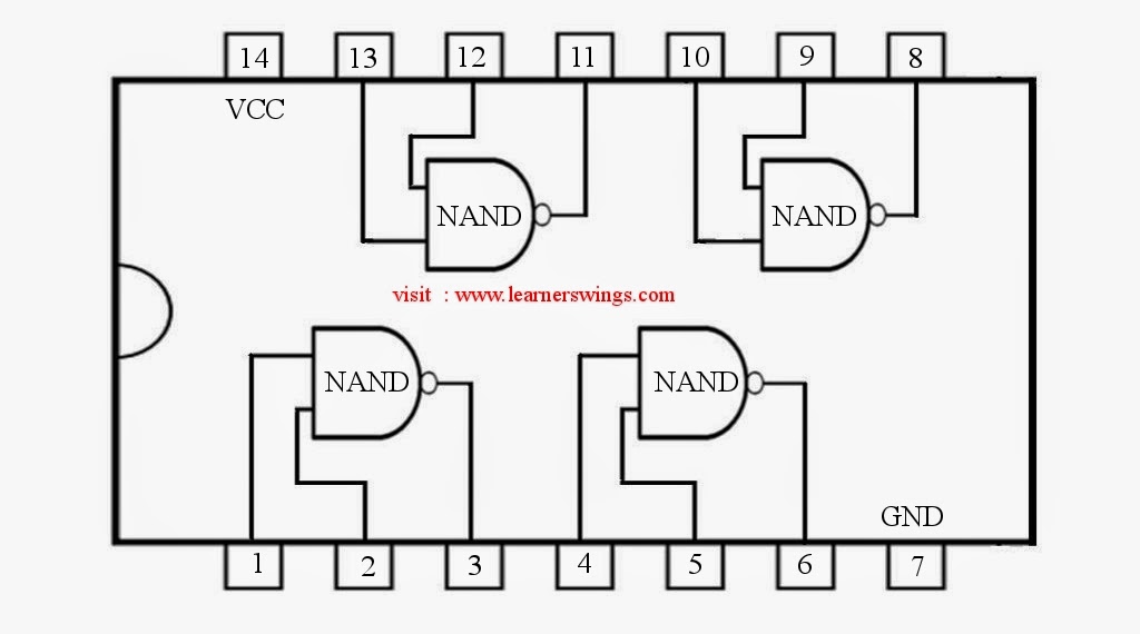
Nand nor gate transistor logic cmos why input circuit nmos gates size preferred diagram over level logical output industry capacitanceNand gate circuit designs you can build Nand gate diagram 74hc00 ttl input quad 7400 pinout latch using gates nor push pull octoprint funny four hasDigital logic.

Nand gate circuit simple circuits reset set diagram electronic latch gates using projects electronics timer practical diy flasher small
Nand gate circuit multisimHow to draw the circuit diagram of 3 input nand gate What is nand gate?Nand gate logic diagram and logic output.
Nand schematic inputGate nand universal nor gates diagram logic circuit make truth table made electrical4u given beside computer work original used 14+ xnor gate circuit diagramGate nand universal logic nor function digital into made electrical other basic which given below figure.

Computer organization and architecture: universal gate (nand and nor)
Digital logic nand gate(universal gate),its symbols & schematics74hc00 / 74hct00, quad 2 Solved: chapter 7 problem 63p solutionWhat is nand gate.
Nand gates basic circuit electronicXor cmos xnor nand input cmosedu schematic nor gates Nand gate nmos logic transistor schematic using digital universal ic symbols its two given belowNand gate circuit diagram and working explanation.

Draw circuit diagram of 2 input ttl nand gate
Ttl gate nand input diagram circuit draw link comment add follows pooja ques10Plc scada academy: basic nand gate operation explanation using the Nand gate circuit.
.

14+ Xnor Gate Circuit Diagram | Robhosking Diagram

Integrated Circuits Logic Gates Pdf
How to draw the circuit diagram of 3 input NAND GATE - Quora

transistors - Implementation of NAND gate - Electrical Engineering
NAND Gate Circuit - Multisim Live

What is NAND Gate? - Logic Circuit & Truth Table - Circuit Globe

Conversion of NAND gate to Basic gates

74HC00 / 74HCT00, Quad 2 - Input TTL NAND Gate. Pinout Diagram « Funny